electric fuel pump

electric fuel pump
In many modern cars the fuel pump is usually electric and located inside the fuel tank. The pump creates positive pressure in the fuel lines, pushing the gasoline to the engine. The higher gasoline pressure raises the boiling point. Placing the pump in the tank puts the component least likely to handle gasoline vapor well (the pump itself) farthest from the engine, submersed in cool liquid. Another benefit to placing the pump inside the tank is that it is less likely to start a fire. Though electrical components (such as a fuel pump) can spark and ignite fuel vapors, liquid fuel will not explode (see flammability limit) and therefore submerging the pump in the tank is one of the safest places to put it. In most cars, the fuel pump delivers a constant flow of gasoline to the engine; fuel not used is returned to the tank. This further reduces the chance of the fuel boiling, since it is never kept close to the hot engine for too long.ectric fuel pump
An advantage of an electric fuel pump is reduced fuel consumption because it does not have the resistance associated with a mechanical drive and because the fuel supply can be monitored more accurately by the electronic control unit (ECU). Pre-delivery of fuel can also be accomplished by an electric fuel pump because it does not depend on engine rpm. Due to this, rapid engine starting can be implemented to conserve gas. This is particularly important in stop-start systems where the engine turns itself off when it senses no use, such as stopped at a stoplight.
The ignition switch does not carry the power to the fuel pump; instead, it activates a relay which will handle the higher current load. It is common for the fuel pump relay to become oxidized and cease functioning; this is much more common than the actual fuel pump failing. Modern engines utilize solid-state control which allows the fuel pressure to be controlled via pulse-width modulation of the pump voltage. This increases the life of the pump, allows a smaller and lighter device to be used, and reduces electrical load.
Cars with electronic fuel injection have an electronic control unit (ECU) and this may be programmed with safety logic that will shut the electric fuel pump off, even if the engine is running. In the event of a collision this will prevent fuel leaking from any ruptured fuel line. Additionally, cars may have an inertia switch (usually located underneath the front passenger seat) that is "tripped" in the event of an impact, or a roll-over valve that will shut off the fuel pump in case the car rolls over.
Some ECUs may also be programmed to shut off the fuel pump if they detect low or zero oil pressure, for instance if the engine has suffered a terminal failure (with the subsequent risk of fire in the engine compartment).
The fuel sending unit assembly may be a combination of the electric fuel pump, the filter, the strainer, and the electronic device used to measure the amount of fuel in the tank via a float attached to a sensor which sends data to the dash-mounted fuel gauge. The fuel pump by itself is a relatively inexpensive part. But a mechanic at a garage might have a preference to install the entire unit assembly
Mechanical fuel pump

Mechanical  fuel pump

Prior to the widespread adoption of electronic fuel injection, most carbureted automobile engines used mechanical fuel pumps to transfer fuel from the fuel tank into the fuel bowls of the carburetor. The two most widely used fuel feed pumps are diaphragm and plunger-type mechanical pumps. Diaphragm pumps are a type of positive displacement pump. Diaphragm pumps contain a pump chamber whose volume is increased or decreased by the flexing of a flexible diaphragm, similar to the action of a piston pump. A check valve is located at both the inlet and outlet ports of the pump chamber to force the fuel to flow in one direction only. Specific designs vary, but in the most common configuration, these pumps are typically bolted onto the engine block or head, and the engine's camshaft has an extra eccentric lobe that operates a lever on the pump, either directly or via a pushrod, by pulling the diaphragm to bottom dead center. In doing so, the volume inside the pump chamber increased, causing pressure to decrease.This allows fuel to be pushed into the pump from the tank (caused by atmospheric pressure acting on the fuel in the tank). The return motion of the diaphragm to top dead center is accomplished by a diaphragm spring, during which the fuel in the pump chamber is squeezed through the outlet port and into the carburetor. The pressure at which the fuel is expelled from the pump is thus limited (and therefore regulated) by the force applied by the diaphragm spring.
The carburetor typically contains a float bowl into which the expelled fuel is pumped. When the fuel level in the float bowl exceeds a certain level, the inlet valve to the carburetor will close, preventing the fuel pump from pumping more fuel into the carburetor. At this point, any remaining fuel inside the pump chamber is trapped, unable to exit through the inlet port or outlet port. The diaphragm will continue to allow pressure to the diaphragm, and during the subsequent rotation, the eccentric will pull the diaphragm back to bottom dead center, where it will remain until the inlet valve to the carburetor reopens.
Because one side of the pump diaphragm contains fuel under pressure and the other side is connected to the crankcase of the engine, if the diaphragm splits (a common failure), it can leak fuel into the crankcase. The capacity of both mechanical and electric fuel pump is measured in psi (which stands for pounds per square inch). Usually, this unit is the general measurement for pressure, yet it has slightly different meaning, when talking about fuel pumps[2]. In this context it denotes the speed, at which the pump delivers fuel from the tank to the engine. This is one of fuel pump characteristics. The higher pressure is, the faster fuel flows.

JET ENGINE WORKING

jet engine working


Jet engines move the airplane forward with a great force that is produced by a tremendous thrust and causes the plane to fly very fast.


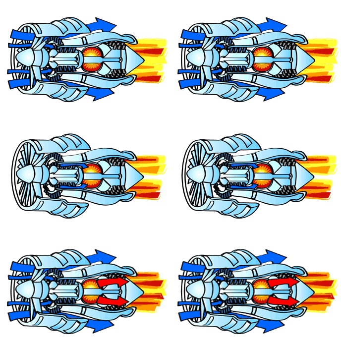
All jet engines, which are also called gas turbines, work on the same principle. The engine sucks air in at the front with a fan. A compressor raises the pressure of the air. The compressor is made with many blades attached to a shaft. The blades spin at high speed and compress or squeeze the air. The compressed air is then sprayed with fuel and an electric spark lights the mixture. The burning gases expand and blast out through the nozzle, at the back of the engine. As the jets of gas shoot backward, the engine and the aircraft are thrust forward. As the hot air is going to the nozzle, it passes through another group of blades called the turbine. The turbine is attached to the same shaft as the compressor. Spinning the turbine causes the compressor to spin.
The image below shows how the air flows through the engine. The air goes through the core of the engine as well as around the core. This causes some of the air to be very hot and some to be cooler. The cooler air then mixes with the hot air at the engine exit area.
 An animated image of a jet engine to show how the air flows through the engine.

This is a picture of how the air flows through an engine

What is Thrust?

Thrust is the forward force that pushes the engine and, therefore, the airplane forward. Sir Isaac Newton discovered that for "every action there is an equal and opposite reaction." An engine uses this principle. The engine takes in a large volume of air. The air is heated and compressed and slowed down. The air is forced through many spinning blades. By mixing this air with jet fuel, the temperature of the air can be as high as three thousand degrees. The power of the air is used to turn the turbine. Finally, when the air leaves, it pushes backward out of the engine. This causes the plane to move forward.

Parts of a Jet Engine

Engine Parts: Fan, Compressor, Combustor, Turbine, Mixer, Nozzle
Fan - The fan is the first component in a turbofan. The large spinning fan sucks in large quantities of air. Most blades of the fan are made of titanium. It then speeds this air up and splits it into two parts. One part continues through the "core" or center of the engine, where it is acted upon by the other engine components.
The second part "bypasses" the core of the engine. It goes through a duct that surrounds the core to the back of the engine where it produces much of the force that propels the airplane forward. This cooler air helps to quiet the engine as well as adding thrust to the engine.

Compressor - The compressor is the first component in the engine core. The compressor is made up of fans with many blades and attached to a shaft. The compressor squeezes the air that enters it into progressively smaller areas, resulting in an increase in the air pressure. This results in an increase in the energy potential of the air. The squashed air is forced into the combustion chamber.

Combustor - In the combustor the air is mixed with fuel and then ignited. There are as many as 20 nozzles to spray fuel into the airstream. The mixture of air and fuel catches fire. This provides a high temperature, high-energy airflow. The fuel burns with the oxygen in the compressed air, producing hot expanding gases. The inside of the combustor is often made of ceramic materials to provide a heat-resistant chamber. The heat can reach 2700°.

Turbine - The high-energy airflow coming out of the combustor goes into the turbine, causing the turbine blades to rotate. The turbines are linked by a shaft to turn the blades in the compressor and to spin the intake fan at the front. This rotation takes some energy from the high-energy flow that is used to drive the fan and the compressor. The gases produced in the combustion chamber move through the turbine and spin its blades. The turbines of the jet spin around thousands of times. They are fixed on shafts which have several sets of ball-bearing in between them.

Nozzle - The nozzle is the exhaust duct of the engine. This is the engine part which actually produces the thrust for the plane. The energy depleted airflow that passed the turbine, in addition to the colder air that bypassed the engine core, produces a force when exiting the nozzle that acts to propel the engine, and therefore the airplane, forward. The combination of the hot air and cold air are expelled and produce an exhaust, which causes a forward thrust. The nozzle may be preceded by a mixer, which combines the high temperature air coming from the engine core with the lower temperature air that was bypassed in the fan. The mixer helps to make the engine quieter.

clasificatiion of engine

TYPES OF IC ENGINE


Classification of I.C. Engines: I.C. engines can be classified as follows:
   1. According to the number of strokes required to complete a cycle:
          (i) 2 stroke engine
          (ii) 4 stroke engine
    2. According to fuel used:
          (i) Petrol engine
          (ii) Diesel engine
         (iii) Gas Engine
   3. According to thermodynamic cycle of operation:
           (i) Constant volume or Otto cycle
          (ii) Constant Pressure or Diesel cycle
         (iii) Mixed or Dual cycle
  4. According to the ignition system used:
          (i) Spark Ignition engine
          (ii) Compression Ignition Engine
  5. According to the number of cylinders:
         (i) Single cylinder engine
         (ii) Multi Cylinder engine
  6. According to arrangement of cylinders:
         (i) Vertical engine
        (ii) Horizontal engine
        (iii) In line engines
        (iv) V engines
         (v) Radial engine
   7. According to the cooling system:
        (i) Air cooled engine
       (ii) Water cooled engine
   8. According to the speed of the engine:
        (i) Low Speed (below 400 rpm)
       (ii) Medium Speed (400 to 900 rpm)
       (iii) High Speed (above 900 rpm)
   9. According to lubrication system:
       (i) Splash Lubrication
       (ii) Pressure Lubrication
   10. According to field of application:
      (i) Stationary engine
      (ii) Mobile engine.

4 strok diesel engine how it works


working of  4 stork engine


 FOUR-STROKE CYCLE ENGINES
     •Four Stroke Petrol engine
     •Four Stroke Diesel engine

FOUR STROKE PETROL ENGINE 
      The four stroke-cycles refers to its use in petrol engines, gas engines, light, oil engine and heavy oil engines in which the mixture of air fuel are drawn in the engine cylinder. Since ignition in these engines is due to a spark, therefore they are also called spark ignition engines.


SUCTION STROKE:
      In this Stroke the inlet valve opens and proportionate fuel-air mixture is sucked in the engine cylinder. Thus the piston moves from top dead centre (T.D.C.) to bottom dead centre (B.D.C.). The exhaust valve remains closed through out the stroke.
 
COMPRESSION STROKE:
      In this stroke both the inlet and exhaust valves remain closed during the stroke. The piston moves towards (T.D.C.) and compresses then closed fuel-air mixture drawn. Just before the end of this stroke the operatingplug initiates a spark which ignites the mixture and combustion takes place atconstant pressure.

 POWER STROKE OR EXPANSION STROKE:
    In this stroke both the valves remain closed during the start of this stroke but when the piston just reaches the B.D.C .the exhaust valve opens. When the mixture is ignited by the spark plug the hot gases are produced which drive or throw the piston from T.D.C. to B.D.C. and thus the work is obtained in this stroke.

 EXHAUST STROKE:
   This is the last stroke of the cycle. Here the gases from which the work has been collected become useless after the completion of the expansion stroke and are made to escape through exhaust valve to the atmosphere. This removal of gas is accomplished during this stroke. The piston moves from B.D.C. to T.D.C. and the exhaust gases are driven out of the engine cylinder; this is also called

SCAVENGING

SUCTION STROKE:
          With the movement of the piston from T.D.C. to B.D.C. during this stroke, the inlet valve opens and the air at atmospheric pressure is drawn inside the engine cylinder; the exhaust valve however remains closed. This operation is represented by the line 5-1

 COMPRESSION STROKE:
          The air drawn at atmospheric pressure during the suction stroke is compressed to high pressure and temperature as the piston moves from B.D.C. to T.D.C. Both the inlet and exhaust valves do not open during any part of this stroke. This operation is represented by 1-2 POWER STROKE OR

EXPANSION STROKE:
         As the piston starts moving from T.D.C to B.D.C, the quantity of fuel is injected into the hot compressed air in fine sprays by the fuel injector and it (fuel) starts burning at constant pressure shown by the line 2-3.At the point 3 fuel supply is cut off. The fuel is injected at the end of compression stroke but in actual practice the ignition of the fuel starts before the end of the compression stroke. The hot gases of the cylinder expand adiabatically to point 4.Thus doing work on the piston.

 EXHAUST STROKE:
          The piston moves from the B.D.C. to T.D.C. and the exhaust gases escape to the atmosphere through the exhaust valve. When the piston reaches the T.D.C. the exhaust valve closes and the cycle is completed. This stroke is represented by the line 1-5.

VALVE TIMING DIAGRAM:


two-stroke diesel engine how its work

Dugald Clerk

Two-stroke engine/Inventors
history
The first commercial  two stroke engine involving in-cylinder compression is attributed to Scottish engineer Dugald Clerk, who patented his design in 1881. ... The crankcase-scavenged engine, employing the area below the piston as a charging pump, is generally credited to Englishman Joseph Day.
working
DESCRIPTION :                                                     
TWO-STROKE CYCLE ENGINES
•Two Stroke Petrol engine
•Two Stroke Diesel engine
TWO STROKE ENGINES
In 1878, a British engineer introduced a cycle which could be completed in two strokes of piston rather than four strokes as is the case with the four-stroke cycle engines. In this engine suction and exhaust strokes are eliminated. Here instead of valves, ports are used. The exhaust gases are driven out from engine cylinder by the fresh charge of fuel entering the cylinder nearly at the end of the working stroke.

A two-stroke petrol engine (used in scooters, motor cycles etc.).The cylinder L is connected to a closed crank chamber C.C. During the upward stroke of the piston M, the gases in L are compressed and at the same time fresh air and fuel (petrol) mixture enters the crank chamber through the valve V.
When the piston moves downwards, V closes and the mixture in the crank chamber is compressed the piston is moving upwards and is compressing an explosive change which has previously been supplied

to L. Ignition takes place at the end of the stroke. The piston then travels downwards due to expansion of the gases and near the end of this stroke the piston uncovers the exhaust port (E.P.)and the burnt exhaust gases escape through this port. The transfer port (T.P.) then is uncovered immediately, and the compressed charge from the crank chamber flows into the cylinder and is deflected upwards by the hump provided on the head of the piston.It may be noted that the incoming air-petrol mixture helps the removal of gases from the engine-cylinder; if, in case these exhaust gases do not leave the cylinder ,the fresh charge gets diluted and efficiency of the engine will decrease. The piston then again starts moving from B.D.C. to T.D.C. and the charge gets compressed when E.P. (exhaust port) and T.P. are covered by the piston; thus the cycle is repeated.

ELECTRIC CAR CONCEPT AND FUTURE OF THE AUTOMOBILE

IN OUR PRESENT WORLD ELECTRIC CAR COCEPT IS VERY REQUIRED BECAUSE OF THE LECK OF THE FUELS LIKE PETROL DEASEL ETC, FUTURE OF THE ELECTRIC...